How to Design Counter Using Jk Flip Flop
The synchronous counter counts the number of clock pulses received at its input. Generally, it is constructed using either JK flip flops or T flip flops.
Before learning the design of the synchronous counter, you can go through the construction, operation and timing diagram of the synchronous counter.
Design steps of synchronous counter
- Find the number of flip flops using 2n ≥ N, where N is the number of states and n is the number of flip flops.
- Choose the type of flip flop.
- Draw the state diagram of the counter.
- Draw the excitation table of the selected flip flop and determine the excitation table for the counter.
- Use K-map to derive the flip flop input functions.
Design Problem #1
Design 3-bit synchronous up counter using JK flip flops.
Step 1: Find the number of flip flops.
A flip flop stores only one bit, hence for a 3 bit counter, 3 flip flops(n=3) are needed to design the counter.
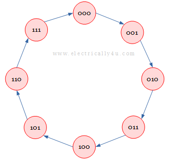
Number of states = 2n = 23 = 8 states(000, 001, 010, 011, 100, 101, 110, 111)
Step 2: Choose the type of flip flop.
Since the type of flip flop is given in the problem, let us use JK flip flops.
Step 3: Draw state diagram for the counter .
The state diagram for the counter is drawn as below.
Step 4: Obtain excitation table for the counter.
We know, the excitation table for JK flip flop is given by,
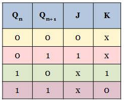
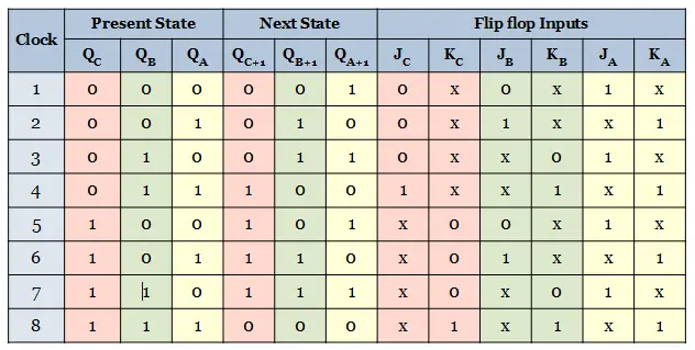
Now the excitation table for the 3-bit synchronous counter is determined from the excitation table of JK flip flop.
The excitation table is framed for 8 states of the counter. Since 3 flip-flops are used in the design, the present state, next state and flip flop inputs for each flip flop are considered.
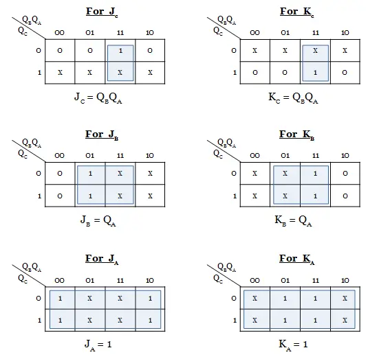
Step 5: Derive the flip flop input functions .
Using Karnaugh maps, the input functions for the 3 flip flops are derived. The present states are the input for all the flip-flops. Since there are three inputs(QC, QB, QA), 8 cell K-map is used.
Learn the minimization of boolean expression using K-map.
Step 6: Draw the logic diagram of the counter.
The logic diagram of the 3-bit synchronous counter is drawn as follows. Draw the 3 JK flip-flops. The common clock input is given to all the flip-flops. The inputs for each flip-flop are drawn as per the logic functions derived in the previous step.

Design Problem #2
Design a Mod-6 synchronous up Counter.
Step 1: Find the number of flip flops.
Mod-6 counter represents that the counter will have 6 states. Thus, N =6.
The number of flip-flops used for counter design is determined using the formula, 2 n ≥ N.
By trial and error method, the value of n is found to be 3. That is the number of flip-flops, n = 3.
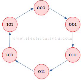
Hence the 6 counter states are 000, 001, 010, 011, 100, 101.
Step 2: Choose the type of flip flop.
Let us choose the JK- flip flop to design the Mod-6 synchronous up counter.
Step 3: Draw state diagram for the counter .
The state diagram for the mod-6 counter with 6 states is drawn as below.
Step 4: Obtain an excitation table for the counter.
The excitation table for JK flip flop is given by,

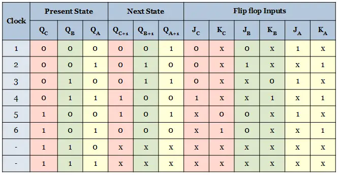
Now the excitation table for the mod-6 synchronous counter is determined from the excitation table of JK flip flop.
The excitation table is framed for 6 states of the counter. Since 3 flip-flops are used in the design, the present state, next state and flip flop inputs for each flip flop are considered.
Step 5: Derive the flip flop input functions .
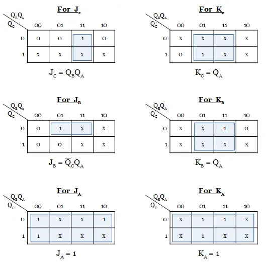
Using K-maps, the input functions for the 3 flip flops are derived. The present states are the input for all the flip-flops. Since there are three inputs(QC, QB, QA), 8 cell K-map is used.
Step 6: Draw the logic diagram of the counter.
The logic diagram of the mod-6 synchronous up counter is drawn as follows. Draw the 3 JK flip-flops. The inputs for each flip-flop are drawn as per the logic functions derived in the previous step.

Design Problem #3
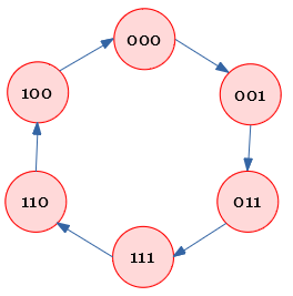
Design a synchronous counter with count sequnce: 000, 001, 011, 111, 110, 100, 000,…
Step 1: Find the number of flip flops.
The given count sequence has 3 bits and there are 6 seven states.
Hence the counter to be designed will have 3 flip-flops.
Step 2: Choose the type of flip flop.
Let us choose JK flip-flops to design the counter.
Step 3: Draw state diagram for the counter .
The state diagram for the given count sequence is drawn as below.
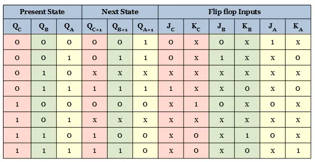
Step 4: Obtain an excitation table for the counter.
The excitation table for the synchronous counter is determined from the excitation table of JK flip flop.
The excitation table is framed for 6 states of the counter. Since 3 flip-flops are used in the design, the present state, next state and flip flop inputs for each flip flop are considered.
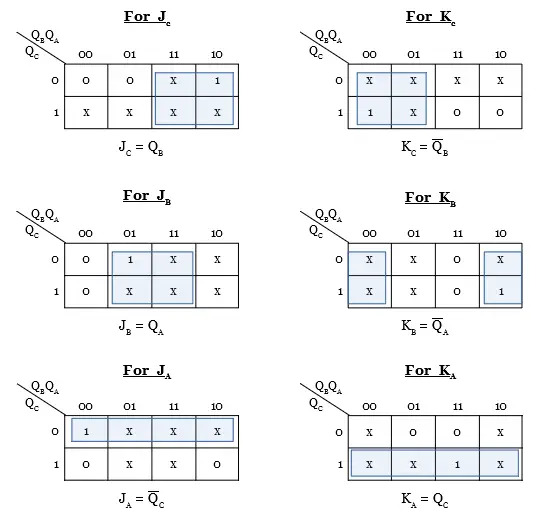
Step 5: Derive the flip flop input functions .
Using K-maps, the input functions for the 3 flip flops are derived. The present states are the input for all the flip-flops. Since there are three inputs(QC, QB, QA), 8 cell K-map is used.
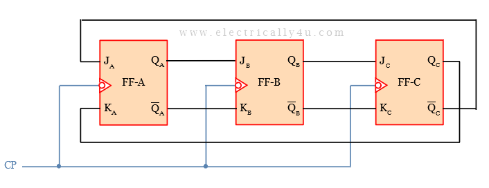
Step 6: Draw the logic diagram of the counter.
The logic diagram of the synchronous up counter or the given count sequence is drawn as follows. Draw the 3 JK flip-flops. The inputs for each flip-flop are drawn as per the logic functions derived in the previous step.
An Assistant Professor in the Department of Electrical and Electronics Engineering, Photoshop designer, a blogger and Founder of Electrically4u.
How to Design Counter Using Jk Flip Flop
Source: https://www.electrically4u.com/design-of-synchronous-counter/
0 Response to "How to Design Counter Using Jk Flip Flop"
Enregistrer un commentaire